How to Connect Portable DC Chargers to Existing Networks?

Time:2026-11-11 Author:Aria
0%

Portable DC chargers can add fast-charging capacity where fixed equipment is delayed or demand changes. Yet connecting one is not simply a matter of plugging it in. Existing electrical capacity, communications links, operating procedures, and user access all shape the result. The practical question is how to integrate portable dc chargers into existing networks without creating avoidable risks or disrupting daily operations.

A sound plan begins with a site review. Check available power, cable routes, weather exposure, vehicle movement, and the charger’s data and payment requirements. Confirm compatibility with the network management platform and follow the manufacturer’s installation guidance. A qualified electrical professional should assess the supply and protection equipment before deployment. Small details matter. A cable crossing a vehicle path or a weak mobile signal can undermine an otherwise capable setup.

This guide explains the main connection choices, commissioning checks, and maintenance considerations for portable DC charging. It also looks at how charger data can be monitored alongside existing stations, and what staff may need to do when a unit moves between sites. The first layout may look tidy on paper but prove awkward beside a busy loading bay. That possibility deserves attention. Network compatibility does not guarantee a smooth user experience, and requirements vary by equipment and location. Careful testing, clear operating instructions, and periodic review help turn a temporary charging asset into a dependable part of the wider network.
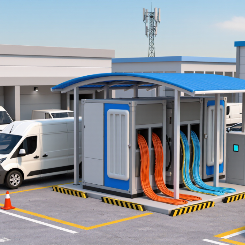
How to Connect Portable DC Chargers to Existing Networks?

Assess Site Capacity Using NEC 625’s 125% EVSE Circuit-Sizing Rule

Before connecting a portable DC charger, check its nameplate and the site’s actual electrical capacity. The input rating matters more than the charger’s advertised output. A unit delivering DC power still draws AC power from the building supply. Record its input voltage, phase, and maximum current. Then compare those values with the panel schedule, feeder rating, and measured site demand.

NEC 625 generally treats EV charging as a continuous load. Size the branch circuit at 125% of the EVSE’s rated input current. For example, a charger drawing 32 amps requires a circuit rated for at least 40 amps, subject to conductor and equipment requirements. Small numbers matter. A 40-amp breaker does not automatically mean the existing panel has 40 amps available. HVAC equipment, kitchen loads, and other chargers may already consume capacity during peak periods.

Have a qualified electrical professional verify the calculation against the locally adopted code edition and equipment instructions. Where the existing service is constrained, approved load management may help control simultaneous demand, but it must be designed and configured correctly. Portable equipment can make installation seem simple. It isn’t always. I would also recheck the load assumptions after a few weeks of real use; operating patterns rarely match the neat estimates on paper.

How to Connect Portable DC Chargers to Existing Networks? - Assess Site Capacity Using NEC 625’s 125% EVSE Circuit-Sizing Rule

Illustrative planning examples for continuous-duty EVSE loads. The minimum circuit ampacity shown is the EVSE input current multiplied by 125%; confirm equipment instructions, the locally adopted NEC edition, and requirements with the authority having jurisdiction.

Example Supply EVSE Input Current Approx. Input Power 125% Minimum Circuit Ampacity Assumed Verified Spare Capacity Preliminary Assessment
A 208 V, single-phase 30 A 6.24 kVA 37.5 A 50 A Capacity exceeds minimum by 12.5 A
B 240 V, single-phase 40 A 9.60 kVA 50 A 60 A Capacity exceeds minimum by 10 A
C 208 V, three-phase 48 A 17.28 kVA 60 A 80 A Capacity exceeds minimum by 20 A
D 480 V, three-phase 30 A 24.94 kVA 37.5 A 45 A Capacity exceeds minimum by 7.5 A
E 240 V, single-phase 40 A 9.60 kVA 50 A 40 A Insufficient by 10 A; reduce load or assess an approved load-management option
Planning notes: Approximate power assumes unity power factor: kVA = volts × amps for single-phase systems, and kVA = √3 × volts × amps for three-phase systems. “Verified spare capacity” is an example value, not a determination based on a particular site. Verify available capacity using the applicable service and feeder load calculations, equipment ratings, measured demand where appropriate, and the EVSE’s nameplate and installation instructions. The 125% figure is a minimum sizing basis for a continuous EVSE load; it does not by itself select the final conductor size or overcurrent-device rating.

Match DC Connectors to IEC 62196-3 Interface Requirements

How to Connect Portable DC Chargers to Existing Networks?

Match DC Connectors to IEC 62196-3 Interface Requirements

Portable DC chargers can join an existing network only when connector compatibility and electrical limits agree. IEC 62196-3:2022 specifies dimensional compatibility for DC and AC/DC vehicle couplers, including plugs, vehicle connectors, and inlets. It does not make every connector interchangeable. Match the exact interface configuration, contact layout, voltage and current ratings, cable temperature limits, and locking geometry against the charger and vehicle documents. Fit is not proof.

The IEA’s Global EV Outlook 2024 reports that public charging points worldwide exceeded four million in 2023, after roughly 40% annual growth. That expansion makes careful interoperability checks practical, not cosmetic. Before deployment, inspect inlet drawings, check latch clearance, and confirm protection and network-control settings with the site operator. IEC 62196-3 covers coupler dimensions; network authorization and charging communication require separate compatibility checks. A label alone is not enough. Field layouts can be awkward, too.

Tips: Compare both sides’ interface designation and full ratings; do not rely on appearance. Test one unit under supervision, then record connector temperature, locking, and fault response before wider rollout.

Check Charger Safety and Control Against IEC 61851-23

A portable DC charger should be treated as part of the site’s charging system, not as a simple plug-in appliance. IEC 61851-23 addresses DC electric vehicle supply equipment, including safety and operating requirements. Check the applicable edition and local adoption before assessing a unit; a reference to the standard alone does not prove compliance. Confirm that the site supply can handle the charger’s rated input without overloading cables or protective devices. Review grounding, insulation monitoring, fault protection, emergency shutdown, and connector condition. Small details matter. A loose connector or unclear shutdown procedure can undermine an otherwise careful installation.

Tips: Compare the charger’s nameplate with the network’s available capacity. Ask a qualified installer to verify protection coordination and earthing on site. Keep test records, and inspect cables for cuts, heat damage, or bent pins. Do not assume that a charger tested in one setup behaves identically elsewhere.

Control and communication deserve equal attention. Check how the charger detects faults, limits output, and stops power when a vehicle disconnects or an emergency stop is pressed. Confirm that status signals and operating limits work with the intended vehicle and network. Some site layouts make cable routing awkward; that can be overlooked during planning. IEC 61851-23 is a useful technical reference, but a competent assessment must also consider the actual installation, connected equipment, and manufacturer documentation. Recheck the arrangement after changes to supply capacity or protective devices.

Connecting a Portable DC Charger: Safety and Control Sequence

Illustrative control sequence: DC output remains unauthorized until site-supply checks, vehicle connection, and applicable communication and safety checks are complete. A stop or fault condition disables output. Verify the charger against the applicable edition of IEC 61851-23, its manufacturer’s instructions, and local electrical requirements; this diagram is not a compliance checklist.

Integrate Communications Through OCPP 2.0.1 and Secure Network Segmentation

Portable DC chargers can join an existing charging network through OCPP 2.0.1, but compatibility needs testing. Confirm that the charger and central management system support the same message features and security profile. A successful connection is not proof that every function works. Test status updates, remote start and stop, fault reporting, and firmware management before deployment. Keep a test charger on a staging network; a failed session is easier to diagnose there.

Tips: Place chargers on a dedicated network segment, separate from office devices and payment systems. Permit only required traffic to approved management endpoints. Use encrypted connections and unique credentials, then review access logs. Small configuration mistakes happen.

For a portable unit, document how it reaches the network at each site. A cellular connection, for example, may need different firewall rules from a wired Ethernet link. Apply network access controls so a charger cannot freely reach unrelated devices. Keep its management interface unavailable from public Wi-Fi. One detail teams sometimes underestimate is time synchronization: incorrect device clocks can complicate certificate checks and log reviews. Check clock settings during commissioning. Re-test after firmware updates or network changes, and record the charger’s OCPP settings, assigned segment, and test results. Good integration is not a one-time checkbox.

Commission Vehicle-to-Charger Communication Using ISO 15118-20

Connecting a portable DC charger to an existing network involves more than plugging in Ethernet. The vehicle and charger must establish a communication session before power flows. ISO 15118-20 defines this exchange, including DC charging and bidirectional power transfer. During commissioning, verify the charger’s communication controller and the vehicle’s EVCC behavior. Small details matter.

Start at the connector. Check wiring, protective earth, and the pilot signal, then confirm PLC communication between the vehicle and charger. The charger acts as the SECC; the vehicle acts as the EVCC. Verify protocol version, session setup, parameter negotiation, and security settings. A successful network ping proves little. Review logs for timeouts, rejected certificates, and mismatched charging limits. Keep a known-good test vehicle and calibrated meter nearby.

When connecting the charger to site systems, distinguish vehicle communication from backend connectivity. Confirm firewall rules, synchronized clocks, and charger status reporting. Test startup, interrupted connections, restarts, and power ramps. Record firmware and configuration changes. The first test may feel untidy; note the gap instead of hiding it. Then test again.

FAQS

Does a connector that fits guarantee compatibility?

No. Compare the exact interface configuration, contact layout, voltage and current ratings, cable limits, and locking geometry. Fit is not proof.

What does IEC 62196-3 cover?

It specifies dimensional requirements for DC and AC/DC vehicle couplers. It does not make every connector interchangeable. Check both sides’ documentation.

What should be checked before connecting a portable charger?

Confirm inlet drawings, latch clearance, electrical ratings, and network settings with the site operator. Labels alone can be misleading.

How can charger safety be assessed at a site?

Check supply capacity, grounding, insulation monitoring, fault protection, and emergency shutdown. Have a qualified installer verify the setup. Small details matter.

What should be tested during a supervised trial?

Record connector temperature, locking behavior, and fault response. Test one unit first. The same charger may behave differently elsewhere.

How can OCPP communication be checked?

Confirm that the charger and management system support matching features and security settings. Test status updates, remote start and stop, fault reports, and firmware management.

How should chargers be separated from other network devices?

Use a dedicated network segment and allow only required traffic to approved endpoints. Use encrypted connections and unique credentials. Mistakes happen.

What network details can be easy to overlook?

Portable chargers may use cellular or Ethernet connections, which can need different firewall rules. Check device clocks; incorrect time can complicate certificate checks and log reviews.

When should integration be tested again?

Re-test after firmware updates or network changes. Keep records of settings, assigned network segments, and test results. It is not a one-time checkbox.

Conclusion

Connecting portable DC chargers to an existing network starts with a careful assessment of the installation site. Review available electrical capacity and apply NEC 625’s 125% EVSE circuit-sizing rule when determining circuit requirements. Confirm that the charger’s DC connector and vehicle interface meet the relevant IEC 62196-3 requirements, and check that its safety and control functions align with IEC 61851-23. These steps help ensure the equipment can operate appropriately within the site’s electrical and charging setup.

To understand how to integrate portable dc chargers into existing networks, plan communications and commissioning alongside the electrical work. Configure charger-to-network communication using OCPP 2.0.1, with secure network segmentation to separate charging equipment from other systems. Then commission vehicle-to-charger communication in accordance with ISO 15118-20, verifying that the charger and vehicle exchange the expected information. A coordinated process covering capacity, interfaces, safety, connectivity, and testing can support a reliable integration.

Aria

Aria

Aria is a dedicated marketing professional with a deep passion for innovative strategies and a keen understanding of our company's product offerings. With a wealth of experience in the industry, Aria excels at crafting engaging content that highlights the unique features and benefits of our......